 English
  한국어
한국어
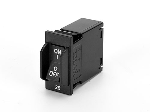
Circuit Breaker BM series
Application
BM series circuit breaker for equipment (hydraulic-magnetic circuit breaker) is used in the power system with rated current from 0.1A to 30A, rated voltage up to AC250V (50/60Hz) or DC80V. It provides overload, short circuit protection. It can also be used for infrequent close or open. The application fields are computer and peripheral equipment, industrial automatic control system, telecom equipment, power supply system, UPS, railroad, marine, spacecraft, elevator, portable power supply and so on.
Specification
2.1 Standards: IEC 60934, GB 17701, UL1077, UL489A
2.2 Rated working voltage: AC240V, AC250V (50/60Hz), DC80V
2.3 Power Frequency Withstand Voltage: 2500V (The withstand voltage of products using in altitude of 4000m is tested under 2500V*1.29 at sea level in the factory.)
2.4 Mechanical/Electrical endurance: 10000/6000, (UL489A approved at electrical endurance: 1000)
2.5 Tripping model: Hydraulic-magnetic type
2.6 Trip-free behaviour: Total trip-free
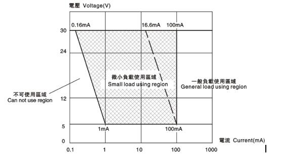
2.7 Auxiliary contact: 3(0.5)A250V/125VAC、3A 30VDC,Auxiliary terminal surface: Silver Plate, contact material: silver plated Ag/Ni 90/10, Please refer to the chart below, use switch within using region
2.8 Rated breaking capacity:
|
Rated voltage (V) |
Rated current (A) |
Number of poles |
Breaking capacity (A) |
|||
|
TUV, CE, CCC |
UL1077 |
UL489A |
||||
|
Icn |
Inc |
|||||
|
DC80 |
0.5-30 |
1,2 |
1000 |
1500 |
1000 U2 |
1000 |
|
AC250 |
0.5-30 |
1,2 |
1000 |
1500 |
/ |
/ |
|
AC120/240 |
0.5-30 |
1,2 |
/ |
/ |
1000 |
/ |
Notice::UL1077 (DC80V)
|
Type |
UG |
FW |
TC |
OL |
SC |
|
OC |
A, B, C, D |
0 |
1 |
0 |
1 kA, U1 |
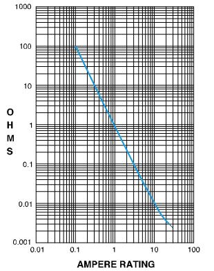
2.9 Resistance, Impedance
|
CURRENT(A) |
TOLERANCE(%) |
|
0.5~20 |
±25% |
|
20.1~30 |
±35% |
Tripping characteristic
4.1 Tripping timetable (in seconds)
|
Current Curves |
100% |
135% |
150% |
200% |
300% |
400% |
600% |
1000% |
|
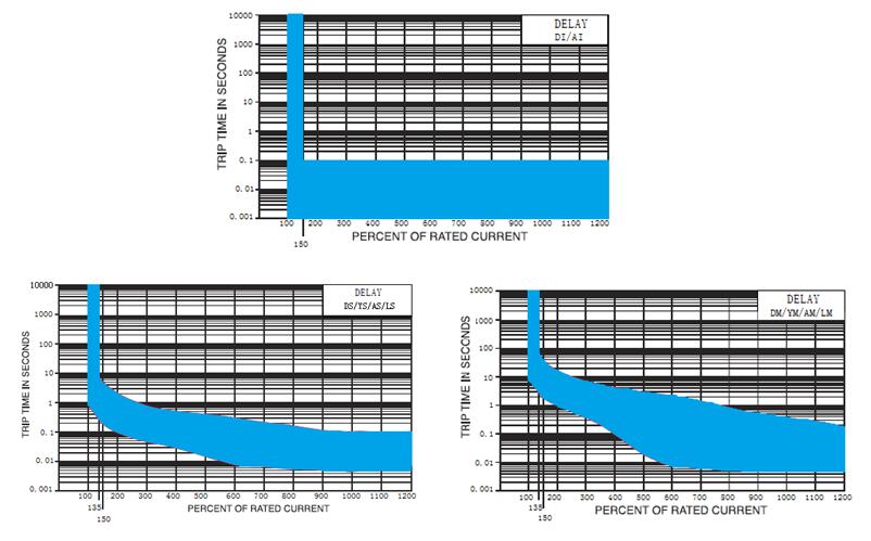
DI/AI |
No trip |
/ |
0.1MAX |
0.1MAX |
0.1MAX |
0.1MAX |
0.1MAX |
0.1MAX |
|
DS/YS/AS/LS |
No trip |
0.3~7 |
0.2~5 |
0.1~2 |
0.004~1 |
0.03~0.5 |
0.008~0.3 |
0.005~0.1 |
|
DM/YM/AM/LM |
No trip |
3~70 |
2~40 |
1~15 |
0.3~10 |
0.1~4 |
0.008~2 |
0.005~0.35 |
4.2 Tripping curves
Model and Implication

|
No. |
Series |
BM |
||||
|
1 |
Product code |
B:Hydraulic electromagnetic circuit breaker |
||||
|
2 |
Series Code |
M:Maximum 30A |
||||
|
3 |
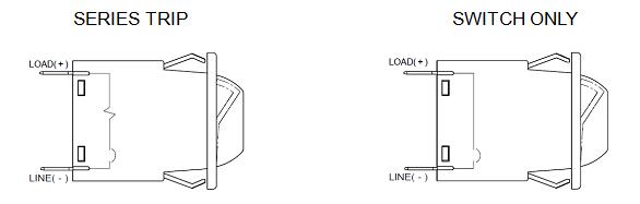
Circuit |
A:Series current trip S:Switch Only |
||||
|
4 |
Actuator code |
R: Rocker |
||||
|
5 |
Number of poles |
1: One-pole 2: Two-pole |
||||
|
6 |
Tripping curve |
DI: DC Instantaneous DS:DC Short DM: DC Medium YS: DC Short Hi-Inrush YM: DC Medium Hi-Inrush AI: AC Instantaneous AS:AC Short AM: DC Medium LS: AC Short Hi-Inrush LM: AC Medium Hi-Inrush |
||||
|
7 |
Rated current (A) |
0.5~30 |
||||
|
8 |
Mounting method |
NO or Q:Snap-in mounting |
||||
|
9 |
Wiring method |
NO or H:Solder-in/ Q.C. tab type B: Push-in stud wiring P:M4 Screw type wiring E: 8-32UNC Screw type wiring J: 8-32UNC Screw wiring with upturned lugs R:M4 Screw wiring with upturned lugs |
||||
|
10 |
Actuator colors and printing code |
Actuator colors |
I-O |
ON-OFF |
Dual |
Printing color |
|
White |
A |
B |
1 |
Black |
||
|
Black |
C |
D |
2 |
White |
||
|
Red |
F |
G |
3 |
White |
||
|
Green |
H |
J |
4 |
White |
||
|
Blue |
K |
L |
5 |
White |
||
|
Yellow |
M |
N |
6 |
Black |
||
|
Gray |
P |
Q |
7 |
Black |
||
|
Orange |
R |
S |
8 |
Black |
||
|
11 |
Indicate Direction |
With current rating at shell : 1: Vertical 2: Horizontal With current rating at actuator: 3:Vertical 4: Horizontal |
||||
|
12 |
Shell color and style |
Shell Color |
Without Rocker guard |
With Rocker guard |
||
|
Black |
B |
2 |
||||
|
Gray |
G |
7 |
||||
|
13 |
Accessory code |
0:No Accessories 1: Auxiliary Switch |
||||
|
14 |
Certificate code |
C: TUV, CE, CCC R: UL1077, TUV, CE, CCC L :UL489A listed, TUV, CE, CCC |
||||
|
15 |
Client code |
XXXXX 5 or more numbers or letters, different customers with special needs, |
||||
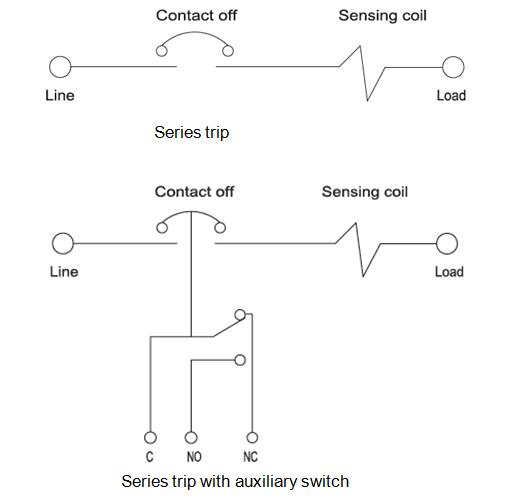
Circuit diagram
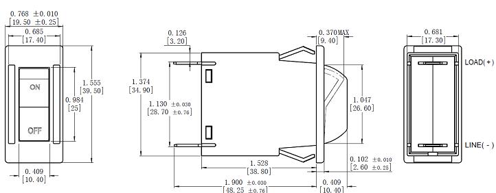
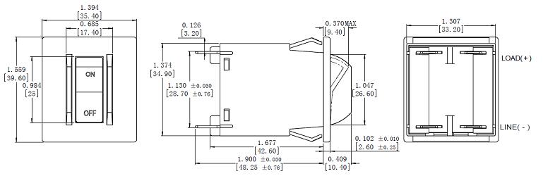
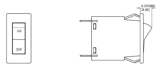
Dimensions
7.1 Rocker Outline dimensions(Tolerance ±0.02in[.51mm] Unless noted)
7.1.1 Single-pole product with guard
7.1.2 Two-pole product with guard
7.1.3 Rocker product without guard(Dimensions also apply to double pole)
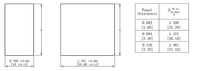
7.2 Panel cutout detail
7.3 Wiring method and dimension(Tolerance ±0.02in[.51mm] Unless noted)
Solder-in /Q.C. tab type Screw type Screw with upturned lugs Push-in stud
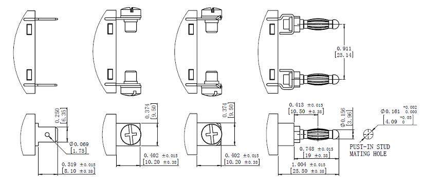
Notice:Recommended tightening torque 1.2N.m
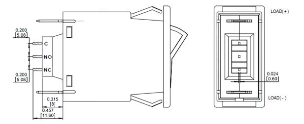
7.4 Auxiliary Switch Outline dimensions (PCB terminal)
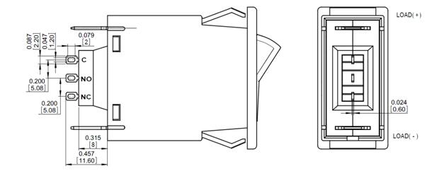
7.5 Auxiliary Switch Outline dimensions (Solder terminal)
7.6 Circuit diagram
Packing and depositing
The products should be stored in the warehouse where there is ventilation. The relative humidity there should not exceed 80%, and the ambient temperature there is between -25℃ to +60℃. In addition, there should not be acidic, alkaline and corrosive gas in the air. The products should not be deposited more than 3 years in the above mentioned conditions since the producing date
Notices
9.1 Do not disassemble the breaker privately.
9.2 Attention to live part when the breaker is energized and avoid touching them.
9.3 Please make sure reliable connection to avoid fault tripping or damage of terminal caused by exceptional heat resulting from unsuitable connection.