English
  한국어
한국어

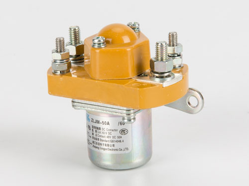
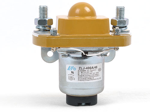
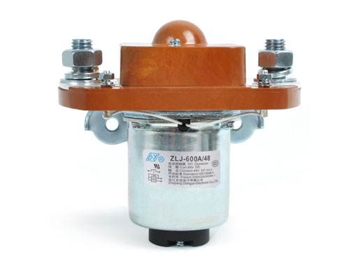
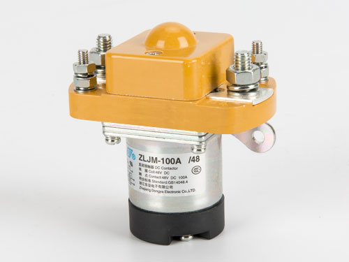
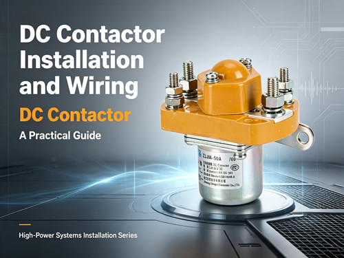
Proper installation and wiring of a DC contactor is just as important as selecting the right model for your application. Even a correctly specified contactor can fail prematurely if it is mounted improperly, wired with incorrect torque, or installed in an unsuitable environment. This guide provides practical, step-by-step instructions for installing and wiring DC contactors in high-power systems.
Why Installation Matters
A DC contactor is an electromechanical switching device designed to handle high direct current loads. Unlike low-voltage relays, DC contactors carry substantial current—often hundreds of amperes—and generate significant heat during operation. Poor installation practices can lead to:
- Loose connections that create high resistance and overheating
- Inadequate heat dissipation that reduces contactor life
- Mechanical stress that affects contact alignment
- Electrical safety hazards including arc flash risks
Following proper installation procedures ensures reliable operation and maximizes the service life of your contactor.
Pre-Installation Checklist
Before beginning the installation, verify the following:
- The contactor rating matches your system voltage and current requirements
- The coil voltage matches your control circuit voltage
- You have the correct tools: torque wrench, multimeter, appropriate screwdrivers
- The mounting surface is clean, flat, and structurally sound
- Adequate clearance exists around the contactor for heat dissipation
- The environment is within the contactor's specified operating conditions
Step 1: Choose the Right Mounting Location
The mounting location significantly affects contactor performance and longevity.
Ventilation and Heat Dissipation
DC contactors generate heat during normal operation, primarily from contact resistance and coil power dissipation. Most contactors are rated at an ambient temperature of 40°C. If mounted in an enclosed space with poor ventilation, the effective current-carrying capacity decreases.
Best practices:
- Mount the contactor in a location with adequate airflow
- Maintain at least 50mm clearance on all sides for air circulation
- Avoid mounting near other heat-generating components
- For high-current applications (above 200A), consider forced cooling
Orientation
Some contactors are designed for specific mounting orientations. The mounting position affects:
- Heat dissipation (heat rises, so vertical mounting may improve convection)
- Contact operation (gravity can affect moving parts in some designs)
- Accessibility for wiring and maintenance
Check the manufacturer's datasheet for orientation recommendations. When in doubt, vertical mounting with terminals facing downward or to the side is generally preferred for heat dissipation.
Vibration and Shock
For mobile applications—electric vehicles, construction machinery, marine systems—the contactor must be mounted securely to withstand vibration. Use:
- Lock washers or thread-locking compound on mounting hardware
- Shock-absorbing brackets if specified
- Regular inspection of mounting hardware tightness
Step 2: Mount the Contactor Securely
Surface Preparation
The mounting surface should be:
- Flat (to prevent mechanical stress on the contactor housing)
- Clean (free of debris, oil, or corrosion)
- Electrically conductive if used for grounding (verify grounding requirements)
Mounting Hardware
Use the correct size and grade of mounting hardware. Most DC contactors have mounting holes or brackets designed for specific bolt sizes. Overtightening mounting bolts can distort the contactor housing and affect contact alignment.
General guidelines:
- Use all mounting points provided
- Tighten mounting hardware evenly in a cross-pattern
- Do not exceed the recommended torque for mounting hardware
Step 3: Wire the Main Power Connections
Main power connections carry the full load current and require the most attention.
Terminal Preparation
Before connecting wires to the contactor terminals:
- Strip insulation to the correct length (typically 10-15mm, depending on terminal type)
- Ensure the exposed conductor is clean and free of oxidation
- For stranded wire, twist strands tightly or use a ferrule
- Do not use anti-oxidation compounds unless specified by the manufacturer
Terminal Torque Specifications
Proper torque is critical for main circuit connections. Insufficient torque creates high-resistance connections that generate heat; excessive torque can damage terminals or strip threads.
For DC contactors, the recommended tightening torque for main circuit terminal screws is typically 4 to 5 N·m. Always verify the specific torque specification for your model.
| Connection Type | Typical Torque Range | Consequence of Under-Torque | Consequence of Over-Torque |
|---|---|---|---|
| Main circuit terminals (stud type) | 4–5 N·m | High resistance, overheating | Terminal damage, stripped threads |
| Main circuit terminals (screw type) | 2–3 N·m | Loose connection, arcing | Damaged threads, cracked housing |
| Control/coil terminals | 0.5–1.0 N·m | Intermittent control signal | Damaged terminal block |
Best practice: Use a calibrated torque wrench for all main circuit connections. Mark each tightened terminal with a torque mark for visual verification during future inspections. Refer to the product datasheet for your specific model's torque requirements.
Wire Sizing
The wire gauge must be adequate for the continuous current rating of the contactor. Undersized wires create excessive voltage drop and heat generation.
General guidelines:
- Use wire rated for at least 125% of the maximum continuous current
- Consider ambient temperature derating for wire ampacity
- Use high-temperature insulation if the contactor operates in hot environments
- Keep wire lengths as short as practical to minimize voltage drop
Step 4: Connect the Coil Control Circuit
The coil circuit controls the contactor's opening and closing. Proper coil wiring ensures reliable actuation.
Coil Voltage Verification
Confirm that the control voltage matches the coil rated voltage. Common DC coil voltages include 12V, 24V, 48V, 72V, 110V, and 220V. Applying incorrect voltage can:
- Under-voltage: cause chattering or failure to close
- Over-voltage: damage the coil or cause excessive heat
Coil Polarity
Some DC contactors have polarized coils—meaning the positive and negative connections must be observed. Check the datasheet or terminal markings. Reversing polarity on a polarized coil may prevent the contactor from operating or damage internal components.
Wiring Considerations for Long Control Runs
For long control wiring runs (over 10 meters), consider:
- Voltage drop: verify coil voltage at the contactor terminals under load
- Wire gauge: use larger gauge wire for longer runs
- Suppression diodes: install across the coil to protect control circuits from flyback voltage
Step 5: Verify Auxiliary Contact Connections (If Applicable)
Many DC contactors include auxiliary contacts that provide status feedback to the control system. These contacts indicate whether the main contacts are open or closed.
Typical auxiliary contact configurations:
- 1NO (normally open) — closes when the contactor is energized
- 1NC (normally closed) — opens when the contactor is energized
- Combination (e.g., 1NO + 1NC)
Auxiliary contacts are typically rated for lower currents (e.g., 1A to 5A) and can be wired directly to PLC inputs or indicator lights.
Step 6: Perform Post-Installation Verification
After completing the installation, perform these verification steps:
- Visual inspection: Check all connections are secure, wires are properly routed, and no tools or debris remain.
- Continuity check: With the contactor de-energized, verify continuity across the main contacts (normally open contacts should show open circuit).
- Coil resistance check: Measure coil resistance and compare to specification.
- Functional test: Apply control voltage and verify the contactor closes properly. Listen for clean, positive closure—no buzzing or chattering.
- Voltage drop measurement: Under load, measure voltage drop across the main contacts. New contacts should show very low voltage drop (typically below 50mV at rated current). Contact resistance above 0.5 mΩ may indicate a problem. Learn more about how to test contact resistance in our detailed guide.
- Temperature check: After running under load for 30 minutes, check terminal temperatures. Excessive heat indicates a connection problem.
Common Installation Mistakes to Avoid
Mistake 1: Using Incorrect Torque
The most common installation error is failing to torque main circuit terminals properly. Under-torqued connections create high resistance, generating heat that can damage the contactor and surrounding components. Over-torqued connections can strip threads or crack the terminal block.
Solution: Always use a calibrated torque wrench and follow the manufacturer's specification.
Mistake 2: Ignoring Heat Dissipation
Mounting a contactor in a confined space without adequate ventilation significantly reduces its current-carrying capacity. A contactor rated for 200A at 40°C may only handle 160-170A at 60°C.
Solution: Provide adequate clearance and ventilation. Consider forced cooling for high-power applications.
Mistake 3: Reversing Coil Polarity
On polarized DC contactors, reversing coil polarity prevents operation. Always verify polarity markings before connecting control wires.
Solution: Check the datasheet and terminal markings. Use color-coded wires for polarity identification.
Mistake 4: Using Undersized Wires
Wires that are too small for the load current create voltage drop and heat, reducing system efficiency and creating fire hazards.
Solution: Size wires according to the continuous current rating with appropriate safety margin.
Mistake 5: Mounting on Uneven Surfaces
Mounting a contactor on an uneven surface can distort the housing, affecting contact alignment and causing premature wear.
Solution: Ensure the mounting surface is flat. Use shims if necessary to achieve a flat mounting.
Installation Quick Reference Checklist
Use this checklist during installation:
- Mounting location has adequate clearance and ventilation
- Mounting surface is flat and clean
- Contact is securely mounted with all mounting points used
- Main circuit wires are correctly sized
- Terminal torque meets specification (4–5 N·m for main terminals)
- Coil voltage matches control circuit
- Coil polarity is correct (if polarized)
- Auxiliary contacts are wired correctly (if used)
- All connections are visually inspected
- Functional test confirms proper operation
- Voltage drop is within specification
- Temperature is normal after load test
FAQ
What torque should I use for DC contactor main terminals?
The recommended tightening torque for main circuit terminal screws on most DC contactors is 4 to 5 N·m. Always verify the specific torque specification for your particular model in the product datasheet.
Can I mount a DC contactor in any orientation?
Not always. Some contactors are designed for specific mounting orientations. Vertical mounting with terminals facing downward or to the side is generally preferred for optimal heat dissipation. Check the manufacturer's datasheet for orientation recommendations.
What happens if I overtighten the terminal connections?
Overtightening can strip threads, crack the terminal block, or damage the contactor housing. This can lead to loose connections over time or complete terminal failure. Always use a calibrated torque wrench.
Why does my DC contactor buzz or chatter when energized?
Buzzing or chattering typically indicates insufficient coil voltage, often due to voltage drop in long control wiring. Check the coil voltage at the contactor terminals under load. If voltage is below the pickup voltage, increase wire gauge or reduce wire length.
Do DC contactor coils have polarity?
Some DC contactors have polarized coils and require correct positive and negative connections. Check the datasheet or terminal markings. Non-polarized coils can be connected in either direction.
How do I know if my contactor installation is safe?
A safe installation uses correctly sized wires, proper terminal torque, adequate clearance for heat dissipation, and secure mounting. After installation, perform functional testing and check for normal operating temperatures. If you are unsure, consult a qualified electrical engineer or contact the manufacturer's technical support team.
Conclusion
Proper installation and wiring are essential for reliable DC contactor operation. The most common installation errors—incorrect terminal torque, inadequate heat dissipation, reversed coil polarity, and undersized wires—can all be avoided by following a systematic installation process.
Start with a suitable mounting location that provides adequate ventilation. Use the correct torque specification (typically 4–5 N·m for main terminals). Verify coil voltage and polarity before applying control power. After installation, perform functional testing and monitor operating temperatures.
For applications requiring high reliability, such as electric vehicles, energy storage systems, and industrial equipment, proper installation is as important as proper selection. Browse our product range to find the right contactor for your system, and reach out to our team if you need installation guidance for your specific application.