English
  한국어
한국어

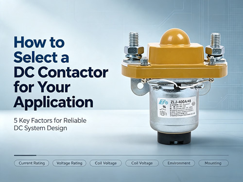
Selecting the right DC contactor is one of the most critical decisions in designing or maintaining a high-power DC system. The wrong choice can lead to contact welding, premature failure, or even safety hazards. This guide walks you through the five key factors you need to evaluate before making a selection, helping you match the contactor to your actual operating conditions rather than just a datasheet.
Why DC Contactor Selection Matters
A DC contactor is an electrically controlled switch designed to handle direct current circuits. Unlike AC contactors, DC contactors must manage the unique challenge of DC arc extinction—because DC current does not naturally cross zero, the arc generated when contacts open is much harder to quench.
Selecting a contactor that is undersized or improperly specified for your application can result in:
- Welded contacts that fail to open
- Excessive contact resistance leading to heat buildup
- Premature wear and reduced service life
- System downtime and safety risks
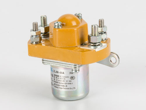
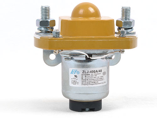
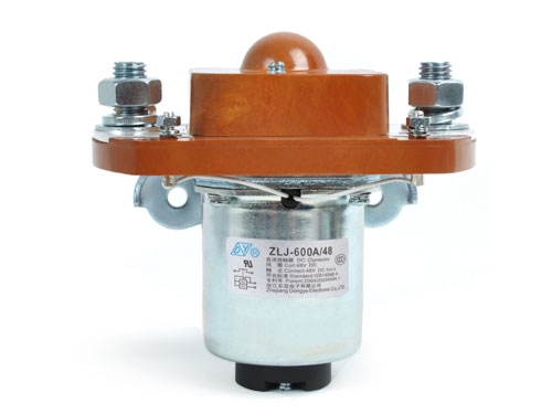
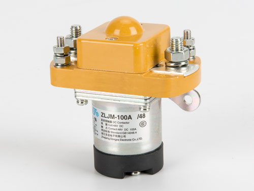
The selection process involves five primary considerations: current rating, voltage rating, coil voltage, application environment, and mounting/configurations. Review the DC contactor product configurations to see available options.
1. Determine the Correct Current Rating
The current rating is the most fundamental specification for any DC contactor. It defines the maximum continuous current the contactor can carry without exceeding its temperature limits.
Continuous vs. Intermittent Current
Most DC contactors are rated for continuous current at a specific ambient temperature (typically 40°C or 50°C). However, real-world operating conditions often differ from test conditions.
| Factor | Consideration |
|---|---|
| Continuous load current | The steady-state current your system draws during normal operation |
| Inrush current | Motors, capacitors, and other loads can draw 5-10x steady-state current during startup |
| Ambient temperature | Higher temperatures reduce the contactor's current-carrying capacity |
| Mounting orientation | Heat dissipation varies with mounting position |
A general rule: select a contactor with a continuous current rating at least 25-30% higher than your maximum expected load current. This provides a safety margin for temperature variations and transient conditions.
Contact Configuration
DC contactors are available in various contact arrangements, including SPST-NO (single-pole single-throw, normally open) and SPST-NC. For most switching applications, SPST-NO is the standard choice. Some models also offer bi-stable (latching) configurations that maintain their state without continuous coil power. Compare available DC contactor models by contact configuration.
2. Verify the Voltage Rating
The voltage rating of a DC contactor must exceed the maximum system voltage, including any voltage spikes that may occur during switching.
Why DC Voltage Rating Matters More Than AC
DC voltage is more difficult to interrupt than AC voltage because DC does not have a zero-crossing point to naturally extinguish the arc. When a DC contactor opens under load, an arc forms between the contacts. The higher the voltage, the more energy is required to extinguish that arc.
| System Voltage | Typical Applications | Contactor Voltage Rating |
|---|---|---|
| 12V / 24V | Automotive, marine | 48V or higher |
| 48V / 72V | Forklifts, AGVs | 100V or higher |
| 400V | Electric vehicles, battery storage | 500V or higher |
| 800V+ | High-end EVs, fast chargers | 1000V or higher |
Always select a contactor with a rated voltage that exceeds your maximum system voltage. For systems with inductive loads (motors, solenoids), consider additional margin to account for voltage spikes during switching.
3. Select the Appropriate Coil Voltage
The coil voltage determines what control signal is needed to actuate the contactor. This is often overlooked but critical for proper integration with your control system.
Common Coil Voltage Options
DC contactor coils are typically available in standard voltages: 12V, 24V, 48V, 72V, 110V, and 220V DC. The choice depends on your available control voltage and the distance between the controller and the contactor.
| Coil Voltage | Best Use Case |
|---|---|
| 12V / 24V | Automotive, mobile equipment, battery-powered systems |
| 48V / 72V | Industrial equipment, forklifts |
| 110V / 220V | Stationary industrial systems, telecom |
Coil Power Dissipation
The coil consumes power whenever the contactor is energized. For continuously energized applications, coil power dissipation becomes a significant factor. Some manufacturers offer bi-stable (latching) contactors that only require power during the switching transient, dramatically reducing steady-state power consumption.
Coil power dissipation typically ranges from 8W to 15W for standard DC contactors. For applications where power efficiency is critical, consider latching contactors that consume power only during switching. Review the product specifications for detailed coil power ratings.
4. Evaluate the Application Environment
The operating environment has a direct impact on contactor performance and longevity. Environmental factors that should influence your selection include:
Temperature
High ambient temperatures reduce the current-carrying capacity of a contactor because heat dissipation becomes less efficient. Most contactors are rated at 40°C ambient. For every 10°C above this, the continuous current rating typically derates by approximately 5-10%.
If your application operates in high-temperature environments—such as engine compartments, desert solar installations, or poorly ventilated enclosures—consider:
- Selecting a contactor with a higher current rating than otherwise needed
- Ensuring adequate ventilation or forced cooling
- Verifying the maximum operating temperature specification
Humidity and Contamination
Moisture, dust, and corrosive contaminants can compromise contactor performance. For applications in harsh environments, look for:
- Hermetically sealed or encapsulated contactors
- Contactors with higher ingress protection (IP) ratings
- Corrosion-resistant materials and finishes
Vibration and Shock
Mobile applications—such as electric vehicles, construction machinery, and marine systems—subject contactors to continuous vibration and occasional shock. In these applications, verify that the contactor's mounting and internal construction are designed to withstand the expected vibration levels.
5. Consider Mounting and Configuration Options
The physical configuration of the contactor must fit your available space and mounting requirements.
Mounting Orientation
Some contactors are designed for specific mounting orientations. The mounting position affects:
- Heat dissipation (contacts generate heat during operation)
- Contact operation (gravity can affect moving parts)
- Accessibility for maintenance and inspection
Terminal Types
DC contactors are available with various terminal configurations:
- Stud terminals (for high-current connections)
- Fast-on terminals (for lower-current applications)
- PCB mount (for integrated designs)
For high-current applications, stud terminals with proper tightening torque are essential. Most manufacturers specify a recommended tightening torque—typically around 4–5 N·m for main circuit terminals.
Auxiliary Contacts
Many DC contactors include auxiliary contacts that provide status feedback to the control system. These can indicate whether the main contacts are open or closed, enabling interlocking and diagnostic functions.
For application-specific mounting requirements, contact our technical team for guidance.
Selection Checklist
Before finalizing your DC contactor selection, run through this checklist:
- Continuous current rating exceeds maximum load current by at least 25%
- Voltage rating exceeds maximum system voltage (including spikes)
- Coil voltage matches available control voltage
- Coil power dissipation is acceptable for your application
- Ambient temperature range is within specifications
- Environmental protection (IP rating, sealing) is adequate
- Mounting orientation and space constraints are satisfied
- Terminal type and size match your wiring requirements
- Auxiliary contacts are specified if feedback is needed
- Applicable certifications (UL, TUV, CE, CCC) are confirmed
Common Selection Mistakes to Avoid
Mistake 1: Using AC Contactors for DC Applications
AC and DC contactors are not interchangeable. AC contactors rely on the zero-crossing of AC current to extinguish arcs, while DC contactors require arc chambers and magnetic blowouts to interrupt DC current. Using an AC contactor in a DC circuit can lead to contact welding and fire hazards.
Mistake 2: Ignoring Inrush Current
Many engineers select contactors based on steady-state current alone, ignoring the inrush current that occurs when capacitive or inductive loads are energized. This can cause contacts to weld during the first switching event.
Mistake 3: Overlooking Coil Voltage Drop
For long control wiring runs, voltage drop can reduce the coil voltage below the pickup voltage, causing the contactor to chatter or fail to close. Always verify coil voltage at the contactor terminals under worst-case conditions.
Mistake 4: Forgetting Temperature Derating
A contactor rated for 100A at 40°C may only handle 80-85A at 60°C. If your enclosure runs hot, the effective current rating is lower than the datasheet value.
FAQ
What is the difference between a DC contactor and a DC relay?
DC contactors and DC relays are both electrically operated switches, but contactors are designed for higher current and voltage applications (typically above 10A). Contactors also include arc suppression features that relays lack, making them suitable for interrupting high-power DC circuits.
Can I use a DC contactor for AC applications?
While DC contactors can sometimes be used for AC applications, it is not recommended. DC contactors are specifically designed for DC arc extinction and may not perform optimally with AC. Always consult the manufacturer's specifications before using a contactor outside its intended application.
How do I test if my DC contactor is failing?
Common signs of contactor failure include excessive contact resistance (above 0.5 mΩ for new units), audible buzzing or chattering, visible contact damage, and failure to open or close reliably. Regular contact resistance measurements can help detect degradation before failure occurs.
What is a bi-stable DC contactor?
A bi-stable (or latching) DC contactor maintains its position without continuous coil power. It uses a permanent magnet or mechanical latch to hold the contacts in position. This design reduces power consumption and heat generation, making it ideal for battery-powered applications.
How often should DC contactors be replaced?
Replacement frequency depends on the application and switching frequency. Contactors used for frequent switching (thousands of operations per day) may need replacement annually, while those in low-cycle applications can last for years. Regular inspection of contact resistance and visual condition is the best way to determine replacement timing.
What certifications should I look for in a DC contactor?
Common certifications include UL, TUV, CE, and CCC. For automotive applications, IATF16949 certification indicates compliance with automotive quality management standards. Always verify that the certification is applicable to your region and application.
Conclusion
Selecting the right DC contactor requires careful evaluation of current and voltage ratings, coil voltage, application environment, and physical configuration. The most common selection errors—using AC contactors for DC, ignoring inrush current, and overlooking temperature derating—can be avoided by following a systematic selection process.
For applications requiring high reliability, such as electric vehicles, energy storage systems, and industrial equipment, working with an experienced manufacturer can help ensure proper selection. Review the available configurations in our product catalog to compare models and specifications.
When in doubt, consult the manufacturer's technical team with your specific operating conditions. The right contactor, properly specified, will provide years of reliable service in your DC power system.