English
  한국어
한국어

In high voltage DC systems, connecting a discharged capacitor bank directly to the supply can cause a massive inrush current that welds contactor contacts or damages downstream components. A pre-charge circuit uses a secondary path with a current-limiting resistor and a dedicated contactor to slowly charge the DC link capacitor before the main contactor closes. This article explains the role of the contactor in this process, how to set the pre-charge timing, and key safety considerations to avoid common failure modes.
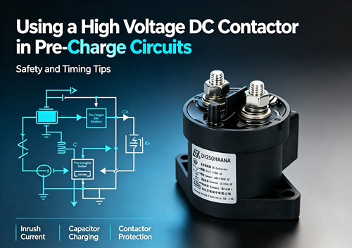
Why a pre-charge circuit is needed in high voltage DC systems
When a high voltage DC bus is first energized, the inverter or converter input capacitors behave like a short circuit momentarily. Without pre-charging, the peak inrush current can be several times the normal operating current, causing:
- Contact welding on the main contactor due to arcing and excessive current during closure.
- Nuisance tripping of upstream protection devices.
- Capacitor stress reducing lifetime.
A pre-charge circuit avoids this by bringing the DC link voltage to a high percentage (typically 90–95%) of the bus voltage before the main contactor engages. This significantly reduces the voltage difference across the main contacts and the inrush current.
Typical pre-charge circuit topology and contactor roles
A basic pre-charge circuit contains three main elements:
- Pre-charge resistor – limits the charging current.
- Pre-charge contactor – connects the resistor path during initial charging.
- Main contactor – bypasses the resistor after pre-charging is complete.
The pre-charge sequence is:
- Pre-charge contactor closes → current flows through the resistor, charging the capacitor.
- DC link voltage rises to a set threshold (e.g., 400 V on a 500 V bus).
- Main contactor closes → the resistor is bypassed; full system current flows through the main contactor.
- Pre-charge contactor opens (optional; some designs keep it closed).
A high voltage DC contactor must be selected for both the pre-charge role (where it carries limited current but must withstand the full voltage) and the main role (full load current). The main contactor must be capable of making the connection at a reduced voltage difference and handling the subsequent load.
Timing considerations and threshold settings
The pre-charge time depends on the capacitance (C), the resistor value (R), and the target voltage ratio. The time constant τ = R × C gives an indication, but exact timing can be calculated using the capacitor charging equation. A typical design aims for 3 to 5 time constants to reach steady state.
- Insufficient pre-charge time → the voltage difference when the main contactor closes is still large, causing a high current surge that can damage the main contactor.
- Excessive pre-charge time → delays system startup without safety benefit; also the pre-charge resistor may overheat if not rated for continuous operation.
Selecting the right contactor for pre-charge applications
Not every contactor is suitable for both pre-charge and main duties. Consider these factors:
| Selection factor | Pre-charge contactor | Main contactor |
|---|---|---|
| Voltage rating | Must withstand full bus voltage | Same as bus voltage |
| Current rating | Limited by resistor, usually low continuous current | Must handle full load and short-circuit conditions |
| Make/break capability | Makes and breaks low current (resistor limited) | Makes at reduced voltage difference; breaks full load |
| Coil economizer | Recommended to reduce coil heating if held for extended time | Essential for continuous-duty contactors |
| Auxiliary contacts | Useful for feedback in the sequencing control | Needed for status monitoring and interlocking |
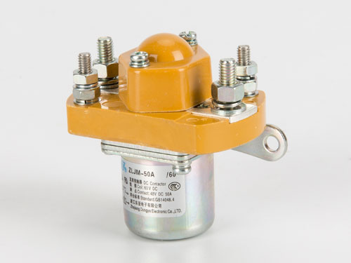
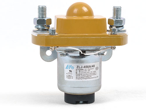
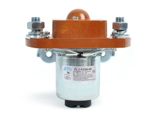
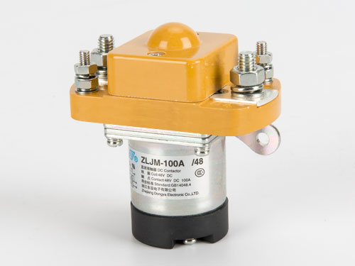
It is common to use the same model of contactor for both pre-charge and main, provided the unit is rated for the full bus voltage and can break the load. Reviewing the manufacturer's specifications for electrical endurance and short-circuit capability helps in making a decision. You can find suitable contactors and compare specifications on the product category page.
Safety practices for pre-charge circuits
- Ensure a positive interlock: The control logic must prevent the main contactor from closing until the pre-charge voltage threshold is reached. Use a voltage sensor or comparator circuit.
- Discharge path: After shutdown, the DC link capacitors must be safely discharged. A discharge resistor or a controlled discharge sequence using the contactor should be part of the design.
- Emergency disconnect: If the pre-charge sequence fails (e.g., resistor open-circuit), the control should time out and disconnect the pre-charge contactor to avoid leaving the system in an undefined state.
- Fusing: Include a fuse in the pre-charge path to protect against a shorted capacitor.
- Coil suppression: Use flyback diodes across contactor coils to prevent voltage spikes that can damage control electronics.
Pre-charge circuit checklist for design and commissioning
- Calculate pre-charge resistor value to limit peak current within contactor and capacitor ratings.
- Verify resistor pulse power rating can handle the charging energy.
- Set pre-charge voltage threshold to at least 90% of bus voltage.
- Test timing: measure the actual voltage rise time and adjust if needed.
- Confirm that the main contactor closes only after the pre-charge threshold is met (hardware interlock recommended).
- Check contactor coil power consumption; if the pre-charge contactor stays energized for long periods, an economizer helps reduce heat.
- After shutdown, verify that capacitors discharge to a safe voltage within the required time.
Frequently Asked Questions
- Q1: Can I use a single contactor with a pre-charge auxiliary switch?
- Some contactor models include auxiliary contacts, but the pre-charge function typically requires two separate power paths. A single contactor cannot substitute for the two-path design unless a dedicated pre-charge module is integrated.
- Q2: What happens if the pre-charge resistor fails open?
- The capacitor will not charge, the voltage threshold will never be reached, and the main contactor will not close. The control circuit should time out and signal a fault. This is a safe failure mode as it prevents uncontrolled connection.
- Q3: How do I prevent the pre-charge contactor from welding during a shorted capacitor?
- The pre-charge resistor limits the current, so welding is unlikely if the resistor is correctly sized. However, a fuse in the pre-charge loop adds protection. Using a contactor with adequate short-circuit withstand rating is also necessary.
- Q4: Is the pre-charge sequence different for bidirectional systems?
- The same principle applies, but both directions of current flow must be considered. In bidirectional applications, the pre-charge circuit may need to charge capacitors from either side, which requires symmetrical design or dual pre-charge paths.
Conclusion
A properly implemented pre-charge circuit using a reliable high voltage DC contactor is essential for the safe operation and long service life of DC power systems. Careful timing, voltage threshold setting, and contactor selection prevent contact welding and protect down-stream components. When designing or troubleshooting a pre-charge sequence, always cross-check the resistor sizing, control interlocking, and the contactor’s voltage and current ratings against the system requirements. For engineers specifying components for pre-charge circuits, Dongya offers a range of contactors that can be configured for various voltage and current demands.