English
  한국어
한국어

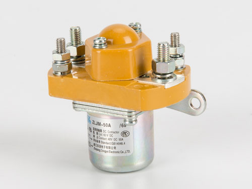
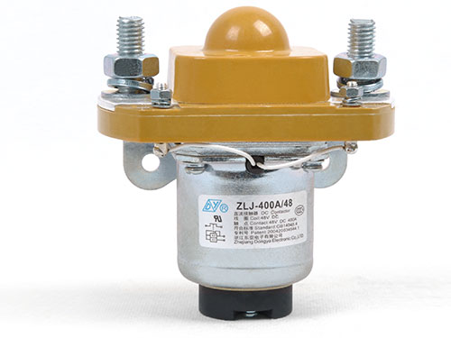
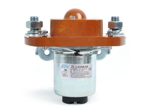
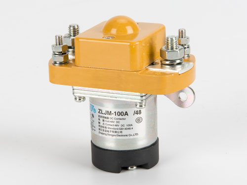
DC contactors control high-current circuits in electric vehicles, photovoltaic energy storage systems, forklifts, and communication power supplies. When one fails unexpectedly, the consequences range from equipment downtime to safety hazards. Most failures do not occur without warning—contact wear progresses gradually, coil insulation degrades over time, and arc chute contamination accumulates across thousands of switching cycles. A structured maintenance routine catches these conditions before they cause contact welding, coil burnout, or insulation breakdown. The following practices apply to industrial DC Contactor units used in low-voltage and high-voltage DC circuits.
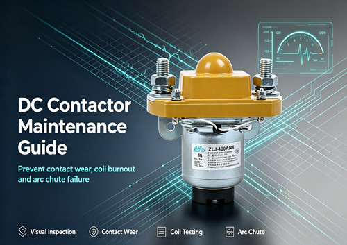
Visual Inspection: The First Line of Defence
A thorough visual inspection performed at scheduled intervals reveals the majority of developing problems. The inspection should cover the contactor housing, main terminals, coil terminals, and arc chute area.
Check the housing for signs of overheating—discolouration, cracking, or deformation of the plastic case indicates that internal temperatures have exceeded the material's rated range. For contactors rated for continuous duty, the housing should show no visible change from its original condition even after extended service. Any blistering or darkening around the main terminal area suggests excessive contact resistance generating localised heat.
Inspect the main terminals for tightness. The manufacturer's specified tightening torque—for many medium-current DC contactors, this falls in the range of 4 to 5 N·m for main circuit terminal screws—must be maintained. A terminal that has loosened by even a fraction of a turn increases contact resistance at the connection point, generating additional heat that accelerates oxidation and further loosening. This cycle continues until the connection fails or the terminal insulator melts.
Coil terminals require the same attention. A loose coil connection causes intermittent contactor operation—the coil may energise inconsistently, causing contact chatter that rapidly destroys the main contacts. Check that each coil terminal screw is secure and that no wire strands have broken free from the terminal block.
Contact Tip Inspection and Wear Measurement
The main contacts are the heart of the contactor, carrying the full load current during operation. Each time the contactor opens under load, a small amount of contact material vaporises due to the arc. Over thousands of operations, this erosion reduces contact thickness until the contact force provided by the spring mechanism is no longer sufficient to maintain low contact resistance.
Contact wear is not always visible without disassembly, but several indirect indicators provide early warning. A gradual increase in contact voltage drop across the closed contacts—measurable with a millivoltmeter while the contactor is under load—indicates that the contact surfaces are degrading. The manufacturer's specification for maximum contact voltage drop at rated current provides the baseline for comparison. Values exceeding this specification by more than 20% warrant further investigation.
For contactors with accessible contacts, a direct visual check reveals the remaining contact thickness. Contacts worn to less than half their original thickness should be replaced. If the contact surface shows uneven wear—with one side significantly thinner than the other—check the contact alignment and spring mechanism. Uneven wear often indicates a mechanical misalignment that will cause premature failure of the replacement contacts as well.
Contact surface condition provides additional information. A smooth, light grey surface is normal for silver alloy contacts. Pitting, blackening, or a rough, granular surface indicates either excessive arcing or contamination. Light pitting can sometimes be cleaned with a soft brush, but contacts that show deep craters or areas where the silver alloy has worn through to the base metal must be replaced. Never file or sand DC contactor contacts—this removes the silver alloy surface layer and exposes the base metal, which has higher resistance and will degrade rapidly.
Coil Resistance Testing and Insulation Checks
The coil is the actuating mechanism that closes the main contacts. Coil failure typically results from either an open circuit caused by winding burnout, or shorted turns that reduce the magnetic force and prevent proper contact closure.
Measure coil resistance with a multimeter at the coil terminals and compare the reading to the manufacturer's specification. A reading that is significantly lower than specification—typically more than 10% deviation—indicates shorted turns within the winding. A reading that shows an open circuit indicates a burned-out coil. Either condition requires coil replacement.
Insulation resistance testing between the coil terminals and the contactor frame provides a check on the condition of the coil insulation. Using a 500V DC insulation tester, measure the resistance between each coil terminal and the metal frame of the contactor. Values below 1 MΩ indicate moisture ingress or insulation degradation that could lead to coil-to-frame shorts. This test is particularly important for contactors installed in outdoor equipment or in humid environments such as marine applications.
The coil's power consumption also provides diagnostic information. For contactors with specified coil power dissipation—commonly 8 to 15 W for medium-current models—an increase in power draw at rated coil voltage often accompanies shorted turns. If the coil runs noticeably hotter than when first installed, resistance and insulation testing should follow.
Arc Chute Cleaning and Inspection
The arc chute—also called the arc extinguishing chamber—contains and extinguishes the arc that forms when the contacts open under load. DC arcs are more difficult to extinguish than AC arcs because the current does not pass through zero, making the arc chute design critical for DC contactor performance. Over time, arc byproducts including metal vapour and carbon deposits accumulate on the arc chute walls and arc splitter plates.
Remove the arc chute according to the manufacturer's procedure and inspect the interior. Black deposits on the splitter plates are normal and can be cleaned with a dry cloth. Do not use solvents or abrasive materials on the arc chute components—the splitter plates rely on specific surface properties to effectively cool and extinguish the arc.
Check the arc chute for cracks or broken splitter plates. A damaged arc chute cannot effectively extinguish the arc, leading to extended arcing times that accelerate contact wear and can cause the arc to escape the chamber. Replace any arc chute that shows physical damage. Also verify that the arc chute is properly seated after reinstallation; a misaligned arc chute can interfere with contact movement or fail to contain the arc.
For operations running contactors in demanding applications—such as frequent switching of inductive loads or operation in dusty environments—increasing the inspection frequency for the arc chute helps prevent arc-related failures. For those reviewing equipment specifications to match maintenance capabilities with application demands, comparing DC switching equipment options can provide insight into which contactor designs are best suited for specific operating conditions and maintenance schedules.
Coil Energisation Test and Contact Operation Check
A functional test of the contactor's operation complements the electrical measurements. Energise the coil at its rated voltage and observe the contact closure. The contacts should close cleanly with a single, firm motion—not bounce or chatter. Contact bounce during closure creates multiple arc events that multiply contact wear.
Listen to the contactor during energisation. A loud hum or buzzing sound indicates that the magnetic circuit is not seating properly. This can result from dirt on the pole faces, a damaged shading ring, or insufficient coil voltage. A contactor that hums in operation will eventually develop contact welding or coil failure.
Measure the pull-in voltage—the minimum coil voltage at which the contactor closes reliably. This value should be within the manufacturer's specified range, typically 70% to 85% of the rated coil voltage for most DC contactors. A pull-in voltage significantly higher than specification indicates either mechanical binding in the contact mechanism or a weakening coil.
Also measure the drop-out voltage—the coil voltage at which the contacts open. A drop-out voltage that is too high can cause nuisance tripping during voltage dips in the control circuit. A drop-out voltage that is too low may prevent the contactor from opening when commanded, creating a safety hazard.
Environmental Considerations in Maintenance
The operating environment directly affects maintenance requirements. Contactors installed in dusty or high-vibration environments—such as construction equipment, marine vessels, or mining machinery—require more frequent inspection than those in clean, climate-controlled electrical rooms.
For outdoor installations, check that enclosure seals and cable glands remain intact. Moisture ingress accelerates contact oxidation and can cause tracking across insulated surfaces. Silica gel breather drains on sealed enclosures should be checked and replaced according to the manufacturer's schedule.
For contactors in photovoltaic energy storage systems, note that these applications often involve frequent switching at high DC voltages. The arc energy increases with voltage, accelerating contact wear and arc chute contamination. Maintenance intervals for PV and ESS contactors should be shorter than for contactors in less demanding applications.
Maintenance Records and Predictive Replacement
A maintenance log that records contact voltage drop, coil resistance, insulation resistance, and visual observations for each contactor creates a trend history. This data allows maintenance planners to identify contactors that are degrading faster than their peers—often pointing to an application-specific stress that can be addressed—and to schedule replacement during planned downtime rather than in response to a failure. For contactors in critical service, reviewing DC contactor specifications and replacement options ahead of scheduled maintenance ensures that replacement units are available when needed.