English
  한국어
한국어

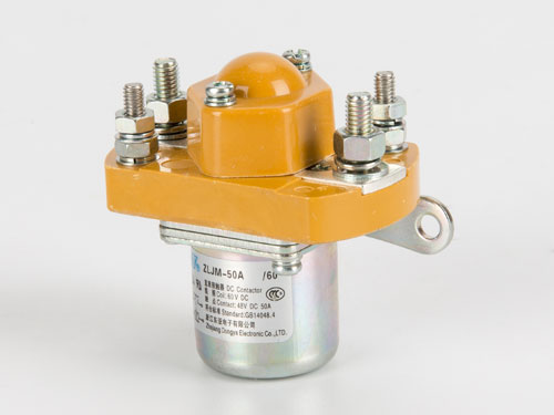
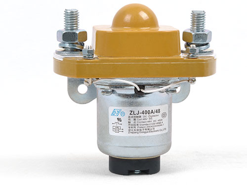
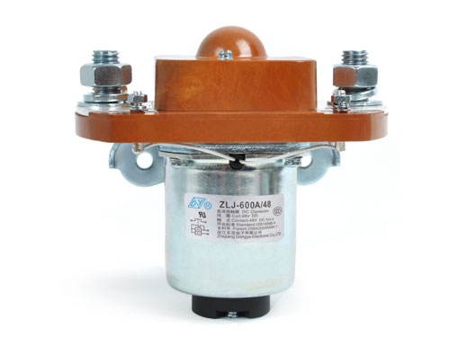
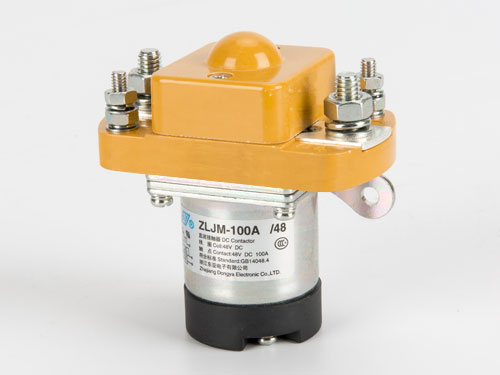
In any system that stores, converts, or delivers substantial DC power—whether it is a 400 V battery pack in an electric bus, a 150 kW fast charger, or a photovoltaic array feeding a grid‑tie inverter—there is a component whose job is both simple and safety‑critical: it must connect and disconnect the high‑current circuit reliably, thousands of times, without welding its contacts or failing to break an arc. A DC Contactor is the electromagnetic switching device that performs this function, and it has become a cornerstone of modern electrification. As the power levels in electric vehicles, charging infrastructure, and renewable energy systems continue to rise, understanding where and how these devices are used helps engineers specify the correct ratings and configurations for their particular application.
Here are the five application areas where DC switching components are most critical, and what each one demands from the device in terms of current rating, voltage withstand, and operational characteristics.
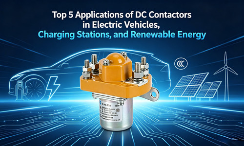
Application 1: Electric Vehicle Battery Isolation
The primary battery pack in an electric vehicle must be able to be completely disconnected from the rest of the high‑voltage system when the vehicle is parked, during charging, or when a fault is detected by the battery management system. The main switching device—often a pair of relays in series with both the positive and negative battery terminals—serves as the primary isolation barrier.
This application places several demanding requirements on the switching device. It must carry the motor drive current continuously without excessive heat generation. It must withstand the inrush current that occurs when the motor controller's DC‑link capacitors charge at power‑on. It must be able to break the full load current under worst‑case conditions, and it must do all of this with minimal coil power consumption because every watt dissipated in the coil is taken from the vehicle's traction battery.
Application 2: DC Fast Charging Stations
A DC fast charger bypasses the vehicle's on‑board charger and feeds DC power directly to the battery. The output of the charging station must be isolated from the vehicle until the charge connector is securely mated and the communication handshake between the vehicle and the charger is complete. A high‑voltage DC relay at the charger output serves as this isolation switch.
The switching device in a charging station operates under different conditions from the one in the vehicle. It must carry high continuous current—often 125 A to 500 A—for the duration of a charge session, which can last 30 minutes or more. It must also be capable of breaking the load current under emergency stop conditions, and it must withstand voltage transients that can occur when the charge cable is disconnected under load. The coil is typically energised for the entire charging session, so low holding power is an important efficiency consideration.
Application 3: Renewable Energy System Disconnect
In a photovoltaic solar installation, a DC disconnect switch is required between the solar array and the inverter. This switch allows the array to be isolated for maintenance, and in many installations it is integrated into a rapid shutdown system that de‑energises the array in the event of a fire or other emergency.
The switching device in this application must be rated for the full open‑circuit voltage of the string—which can reach 600 V to 1500 V in utility‑scale installations—and for the short‑circuit current of the array. It must be able to break a DC fault current, which places greater demands on the arc‑extinguishing mechanism than breaking an AC current of the same magnitude. Non‑polarized designs, which can interrupt current in either direction, are often preferred for this application because the current direction can reverse in certain fault conditions or in systems with battery storage.
Application 4: Energy Storage System Battery Management
Grid‑scale battery energy storage systems use racks of lithium‑ion battery modules, each of which must be individually isolable. A DC switching device on each module allows a faulty module to be taken offline while the rest of the system continues to operate. This modular isolation capability is essential for maintaining uptime in multi‑megawatt storage installations.
The switching components in this application must combine a compact footprint with the ability to carry and interrupt the module's full discharge current. They must also operate reliably in a high‑temperature environment, because battery racks generate significant heat during charge and discharge cycles. Magnetic latching designs, which hold the contacts closed with a permanent magnet after a brief coil pulse, are increasingly common in this application because they eliminate the continuous coil power draw and reduce the thermal load inside the enclosure. For storage system integrators looking to source latching and non‑latching DC power relays for modular battery racks, the availability of both configurations from a single supplier simplifies procurement and ensures consistent performance across all modules.
Application 5: Industrial DC Motor Control and Distribution
Beyond the electrification and renewable energy sectors, DC switching devices remain essential in industrial applications such as DC motor control in material handling equipment, DC power distribution in telecom central offices, and battery backup systems for critical infrastructure. A forklift, for example, uses a series of DC relays to control the traction motor, the hydraulic pump motor, and the power steering motor, each of which draws a different current and has a different duty cycle.
The switching components in these industrial applications must withstand frequent cycling, mechanical shock and vibration, and, in some cases, exposure to dust, moisture, or corrosive atmospheres. A device rated for 100,000 mechanical cycles under laboratory conditions may deliver a shorter service life when exposed to the vibration of a forklift mast or the salt air of a dockside warehouse. Selecting a component with an appropriate environmental rating for the installation site is as important as matching the electrical ratings.
Selection Considerations Across Applications
Across all five application areas, the same set of selection parameters determines whether the switching device will perform reliably: continuous current rating, maximum operating voltage, short‑circuit breaking capacity, coil voltage and power consumption, contact configuration (normally open, normally closed, or changeover), and environmental protection. A supplier that provides detailed specifications for each of these parameters, along with certification to recognised standards such as UL and CE, reduces the engineering effort required to qualify the component for the final application. For a comprehensive range of electromagnetic DC switching devices with documented performance specifications, the manufacturer's data sheets provide the necessary information to match the component to the application's specific requirements.
The five applications above represent the fastest‑growing sectors for DC power switching technology, and in each case the switching component is not a generic part but a carefully specified element of a larger safety and control system. When the correct ratings are selected, and the installation is properly engineered, the DC switching device operates silently, reliably, and almost invisibly—connecting and disconnecting thousands of times without ever drawing attention to itself. That invisibility is the mark of a component that has been correctly applied.