English
 한국어


When a battery energy storage system reports a current value that does not match what the contactor and circuit breaker appear to be doing, the problem is not always in the device that first looks wrong. A DC shunt may be producing a valid voltage signal that is being corrupted before the BMS reads it; a contactor may be receiving an open command but not carrying current as expected; or a breaker may be operating correctly while the measurement chain reports a different story. This article provides a layered diagnostic sequence for separating measurement-side errors from switching-side and protection-side issues in ESS current paths.
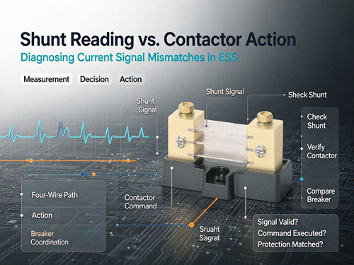
The Signal–Decision–Action Chain in an ESS Current Path
An ESS current path contains three functional layers that are often discussed separately but must be diagnosed together:
- Measurement layer — the shunt converts load current into a millivolt signal.
- Decision layer — the BMS or controller interprets that signal, compares it against thresholds, and issues commands.
- Action layer — the contactor performs commanded switching; the circuit breaker provides protective interruption independent of the command path.
A symptom that appears as “wrong current reading” or “contactor did not open” can originate at any of these three layers, and the diagnostic sequence should follow the signal from measurement to action, not start at the most visible device.
Layer 1: Is the Shunt Signal Itself Credible?
Before attributing a current mismatch to the contactor or breaker, confirm that the shunt signal reaching the BMS is physically valid. A precision DC shunt generates a small voltage drop—typically 50 mV, 75 mV, or 100 mV at rated current—and at a 500 A / 50 mV rating the element resistance is only 100 µΩ. At that signal level, a contact resistance of 0.1 mΩ in the measurement path represents a 100% error at full scale.
The first diagnostic question is therefore not “is the shunt accurate?” but “is the shunt being measured through a clean four-wire path?” A four-wire (Kelvin) connection separates the current-carrying path from the voltage-sense path, so terminal and lug resistance are excluded from the measurement. If the sense leads share terminals with the load cables, or if the sense connections have developed oxidation or loosened torque, the BMS can report a current that is higher or lower than the actual load without any fault in the shunt element itself. In a system where the contactor appears not to be carrying current but the BMS shows a nonzero value, the sense wiring should be checked before the contactor is suspected.
Layer 2: Is the Contactor Responding to the Command?
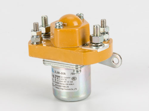
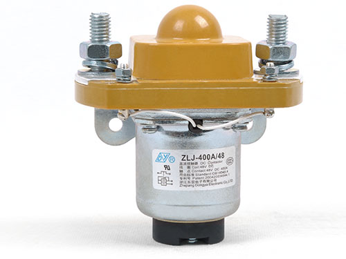
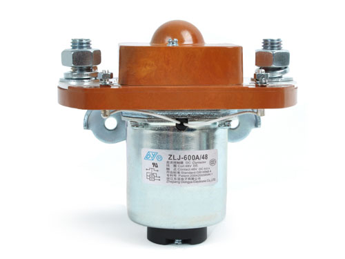
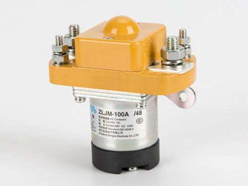
If the shunt signal is credible and the BMS shows current flowing when the contactor is commanded open, or shows no current when the contactor is commanded closed, the next layer is the contactor’s response to its coil command. A contactor can fail to open because the coil circuit is not receiving the command, because the coil is open or shorted, or because the mechanism is mechanically bound despite coil energization. Coil current and pick-up/release behavior are more diagnostic than the commanded state alone: a coil that draws current but does not change contact state points to a mechanical or contact-welding issue, while a coil with no current points to the control circuit or coil itself.
DC contactors used in ESS main paths are typically applied under IEC 60947-4-1 DC-1 duty (non-inductive or slightly inductive loads, L/R ≤ 1 ms), but the command path and the current path are separate circuits. A contactor that is electrically commanded to open but remains closed will continue to carry current, and the shunt will correctly report that current—the mismatch is in the action layer, not the measurement layer.
Layer 3: Is the Breaker Providing Coordinated Protection?
The circuit breaker operates on a different principle from the contactor: it responds to overcurrent magnitude and duration, not to a command from the BMS. If a hydraulic circuit breaker trips while the BMS reports normal current, or fails to trip during an overcurrent event that the BMS detects, the question is whether the shunt signal and the breaker’s sensing element are seeing the same current.
Hydraulic-magnetic breakers use a solenoid and a viscous fluid to produce inverse time-current response, and their trip point is relatively stable against ambient temperature compared with thermal breakers. However, the breaker’s current-sensing element and the shunt are separate devices in the same path. A breaker that trips below its expected threshold, or a shunt that reads high, can produce the same symptom—a protection action that does not match the BMS record. The diagnostic sequence should compare the breaker’s trip event against the shunt-recorded current at the moment of trip, not against the BMS’s post-event summary alone.
Layered Diagnostic Table for ESS Current Signal Mismatches
| Symptom | First layer to check | What to confirm | If normal, move to |
|---|---|---|---|
| BMS shows current when contactor is commanded open | Measurement (shunt signal path) | Four-wire sense integrity; no shared terminals with load path | Contactor action (coil, mechanism) |
| BMS shows no current when contactor is commanded closed | Measurement (shunt signal path) | Sense lead continuity; ADC input not saturated | Contactor action (contact state) |
| Contactors commanded open but current does not drop | Action (contactor) | Coil current present; mechanical binding or contact welding | Breaker / upstream isolation |
| Breaker trips while BMS reports normal current | Measurement vs protection comparison | Shunt-recorded current at trip instant; breaker rating and curve | Breaker sensing element or coordination |
| BMS current reading drifts over time | Measurement (shunt) | Temperature at shunt element; four-wire path stability | BMS temperature compensation |
| Protection action occurs at unexpected current level | Coordination | Breaker curve vs shunt full-scale; both devices share the same path | Protection design review |
This table is intended for diagnostic sequencing, not for live intervention. Any check that requires opening the current path should follow lockout and isolation procedures.
FAQ
If the BMS current reading is wrong, should the shunt be replaced first?
Not necessarily. The shunt element is only one part of the measurement chain. The four-wire sense path, terminal torque, and ADC input should be confirmed before replacing the shunt, because a sense-wiring error can produce the same symptom as a failed shunt.
Can a contactor be commanded open but still carry current?
Yes. If the coil circuit is interrupted but the main contacts remain welded or mechanically bound, the contactor can appear “open” from the control side while the current path remains closed. The shunt will continue to report current in that condition.
Does a hydraulic breaker trip on the same signal that the BMS uses?
No. The breaker responds to current through its own sensing element, not to the BMS command. The shunt and the breaker sense current independently, so a coordination check must compare the two records rather than assume one represents the other.
How can a shunt reading be “wrong” if the shunt is a precision component?
Precision refers to the element’s resistance stability, not to the entire measurement path. A four-wire connection is required to exclude terminal and lug resistance; without it, a 0.1 mΩ contact resistance against a 100 µΩ shunt can produce a full-scale error.
When does a current mismatch require supplier involvement rather than field diagnosis?
If the shunt signal is confirmed valid through a four-wire path and the contactor coil behavior is normal, but the BMS still reports a value that cannot be explained by load conditions, the next step is to compare the measured values against the product-specific specifications. Contact the Dongya technical team with the shunt model, contactor model, and recorded signal values before changing components.
Conclusion
A current signal mismatch in an ESS is a system-level symptom, not a verdict on a single component. The diagnostic order should follow the chain: confirm the shunt signal through a four-wire path, then confirm the contactor’s response to its coil command, then compare the breaker’s action against the current record at the moment of operation. Starting at the most visible device—usually the contactor—often leads to replacing a component that was responding correctly to a corrupted signal. Review the shunt series specifications to confirm the rated output and wiring configuration for the measurement layer, and use the company profile to confirm the product scope available for the switching and protection layers before a system-level review.