English
 한국어


A high voltage DC contactor in an energy storage system rarely fails without precursor signals. Rising contact resistance, localized terminal heat, abnormal coil current, and arc-chamber contamination typically appear before an open circuit, welded contact, or unplanned isolation event. This article lists the degradation indicators that can be observed during routine ESS maintenance and provides a field inspection sequence for confirming whether a contactor should remain in service, be monitored more closely, or be scheduled for replacement.
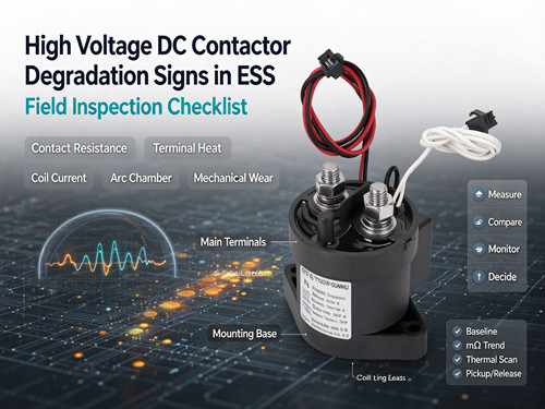
Why ESS Contactors Degrade Differently
Battery energy storage systems impose a specific combination of conditions on DC contactors: continuous current for hours during charge or discharge, system voltages at 800 V, 1000 V, or 1500 V DC, bidirectional current flow, and installation inside sealed enclosures where internal air temperature can exceed external ambient. Under IEC 60947-4-1, ESS main contactor duty typically aligns with DC-1 (non-inductive or slightly inductive loads, L/R ≤ 1 ms), but the continuous thermal load and enclosure heat concentration still drive long-term degradation. The degradation process is gradual: contact surfaces erode, contact resistance rises, terminal temperature increases, and coil or arc-control components age. Because the contactor remains electrically functional through much of this process, the only way to act before failure is to measure and compare the signals that change first.
Five Observable Degradation Signals
1. Rising Contact Resistance
Contact resistance is the most direct electrical indicator of contact-surface degradation. For a new high voltage DC contactor, typical contact resistance is in the range of 0.1–0.2 mΩ, with normal operation accepted up to about 0.5 mΩ depending on rating and manufacturer tolerance. When resistance reaches 0.5–1.0 mΩ, the contacts are no longer operating at baseline; cleaning may be possible, and the next inspection interval should be shortened. A value above 1.0 mΩ, or a visible increase greater than 50% from the commissioning baseline, is a replacement trigger. In ESS maintenance, this measurement requires a four-wire micro-ohmmeter or a calibrated voltage-drop method under load; a standard multimeter resistance range does not provide enough test current to resolve small changes reliably. DC contactor product configurations with published contact resistance specifications allow the measured value to be compared against a defined limit rather than an assumed one.
2. Localized Terminal Overheating Without Load Change
A terminal that runs hotter than comparable terminals at the same current points to increased resistance at the connection or contact interface. Visual signs include discoloration, blistering, or darkening around the main terminal area; these indicate that localized heat has exceeded the material’s normal operating range. Thermal imaging during routine load conditions is more informative than a single spot check because it shows whether heat is concentrated at one terminal or distributed evenly. The inspection should compare terminal temperatures across phases or strings under similar current, not against an absolute temperature threshold alone.
3. Abnormal Coil Current or Pick-Up/Release Behavior
Coil current can drift as the coil insulation ages, as the economizer circuit changes its hold current, or as mechanical binding increases the force required to close the contactor. Symptoms include a coil that runs abnormally hot during normal operation, erratic dropout, or an open-circuit coil reading. A rise in coil power consumption at a fixed control voltage may indicate mechanical binding rather than a coil fault itself, so coil current should be interpreted together with pick-up and release behavior and with the mechanical condition of the contactor. In ESS enclosures, coil heat contributes to the internal thermal load; an economizer that fails to switch to low hold current adds continuous heat inside the same sealed space.
4. Arc-Chamber Contamination or Seal Degradation
Ceramic-sealed, gas-filled contactors are designed to extinguish DC arcs by cooling and stretching the arc in a controlled atmosphere. The sealed chamber prevents contact oxidation and stabilizes contact resistance under harsh conditions. However, shipping shock, stress from rigid busbar connections, or thermal cycling can open hairline flaws in the seal or ceramic. A compromised seal does not always produce an immediate failure; it may first appear as slowly rising contact resistance, unstable voltage drop, or visible arc residue around the contact area. Because the internal arc chamber cannot be inspected directly in most field conditions, seal integrity should be treated as a suspect when resistance rises without a corresponding increase in switching operations.
5. Mechanical Wear and Contact Erosion
Repeated switching under load erodes contact material and can change the mechanical travel or opposing force inside the contactor. Research on HVDC contactor degradation has identified degradation of the opposing force as a root cause of decreased pick-up time and increased release time. In the field, mechanical wear may present as a change in operating sound, slower response to coil commands, or visible arc erosion on accessible contact surfaces. These signs are not measurable with a single instrument, but they become actionable when tracked alongside electrical and thermal data.
Field Inspection Checklist for ESS Contactors
| Inspection step | What to check | Indication of degradation | Suggested action |
|---|---|---|---|
| Baseline review | Compare current readings against commissioning records | No baseline available | Establish baseline at the next scheduled maintenance |
| Contact resistance | Measure with four-wire method or voltage drop under load | 0.5–1.0 mΩ; or >50% rise from baseline | Clean if possible; shorten inspection interval |
| Contact resistance — replacement threshold | Compare against manufacturer limit | >1.0 mΩ, or visible increase >50% from baseline | Schedule replacement |
| Terminal temperature | Thermal imaging under similar load across strings | One terminal consistently hotter than comparable terminals | Inspect connection torque and contact interface |
| Coil current and behavior | Measure coil current at rated control voltage; observe pick-up/release | Coil current drift, abnormal heat, erratic dropout | Check economizer circuit and mechanical binding |
| Visual condition | Housing, terminals, arc-chamber area | Discoloration, blistering, carbon dust, cracks | Correlate with resistance and thermal data |
| Switching duty | Review operation count against expected duty | Frequent switching near rated current | Reassess duty against DC-1 assumptions |
This checklist is intended for scheduled maintenance, not for live troubleshooting under fault conditions. Any measurement that requires access to main terminals should follow lockout and isolation procedures.
When to Confirm with the Supplier
If contact resistance is rising but remains below the replacement threshold, or if coil current has changed without a clear mechanical cause, the next step is to confirm the measured values against the product-specific specification. Datasheet ratings are established under defined test conditions; the application engineer’s task is to compare field measurements against those conditions, not against a generic rule. High voltage DC contactor series with published contact resistance and coil data provide the reference values needed for this comparison. For a specific configuration, review the DH200H technical specifications or discuss the measurement conditions with the technical team before changing the maintenance interval or replacing a unit.
FAQ
How often should contact resistance be checked on an ESS contactor?
Industry maintenance practice for high voltage DC contactors recommends recording a baseline at commissioning and repeating the measurement every 6–12 months, or according to the equipment duty cycle. ESS installations with continuous charge/discharge cycles may warrant the shorter end of that range.
Can a contactor with rising resistance still carry rated current?
It may continue to carry current, but the margin between the contact temperature and the material limit is reduced. Resistance in the 0.5–1.0 mΩ range is an inspection and monitoring trigger, not immediate failure; above 1.0 mΩ or a greater than 50% rise from baseline, replacement should be scheduled.
Does a hot terminal always mean the contactor is failing?
Not necessarily. A loose connection, undersized busbar, or unbalanced current can also produce localized heat. Terminal temperature should be compared across comparable terminals and correlated with contact resistance and load current before attributing the heat to contact degradation.
Is coil current a reliable indicator by itself?
No. Coil current changes can come from insulation aging, economizer behavior, or mechanical binding. It is most useful when tracked alongside pick-up/release behavior and mechanical condition, rather than used as a standalone replacement criterion.
What is the difference between DC-1 and higher-duty categories for ESS contactors?
IEC 60947-4-1 defines DC-1 for non-inductive or slightly inductive loads with L/R ≤ 1 ms, while DC-3 and DC-5 cover motor loads with higher time constants. Most ESS main contactor duty falls under DC-1, but the continuous thermal load and enclosure temperature still require verification against the actual installation conditions.
Conclusion
The most reliable time to replace an ESS contactor is before it fails, and the signals that precede failure are measurable. Contact resistance trending above baseline, a terminal running hotter than its peers, coil current drifting without a mechanical explanation, and visible seal or arc-chamber deterioration together provide a practical early-warning picture. The first step is not to choose a new contactor, but to establish a baseline and track these values against the product-specific specification. Review the high-voltage DC contactor range to confirm which parameters are published for each series, and contact the Dongya team when field measurements fall between “normal” and “replace” and a technical confirmation is needed.