English
 한국어


A shunt is often treated as a simple resistor: pass current through it, measure the voltage, divide by resistance. If the shunt is properly selected, correctly wired in a four-terminal configuration, and freshly calibrated, the reading should be accurate. In practice, readings still drift—and the causes are physical, not procedural.
Three mechanisms account for most of the residual error in a well-installed shunt: the temperature coefficient of resistance (TCR), thermoelectric EMF at the sense junctions, and mechanical stress in the resistive element. Each produces a different error signature, and each requires a different mitigation strategy. Understanding them is essential for applications where the shunt output feeds a BMS state-of-charge calculation, a precision current loop, or any long-duration integration.
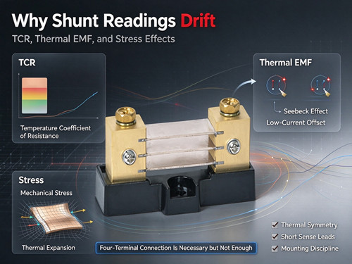
Error Mechanism 1: Temperature Coefficient of Resistance (TCR)
Every resistive material changes resistance with temperature. The question is by how much.
For a precision shunt, the resistive element is typically a manganese-copper alloy such as manganin. Compared with copper or aluminium, whose TCR is on the order of 4000 ppm/°C, manganin's TCR is roughly 400 times better—but it is not zero. Practical manganin shunts exhibit a TCR in the range of roughly 15–20 ppm/°C over typical operating temperatures, and the R(T) curve is not perfectly linear.
A TCR of 15 ppm/°C may sound negligible, but consider what it means at scale. A 10°C temperature rise shifts the resistance by approximately 150 ppm, or 0.015%. That is small in absolute terms, but in a BMS that integrates current over hours to calculate state of charge, a systematic 0.015% bias accumulates. Over a full charge–discharge cycle, the integrated error can shift the SOC estimate by a measurable amount.
The practical implication is not that manganin shunts are unsuitable—they are the standard choice precisely because their TCR is low. The implication is that temperature compensation in firmware is necessary for high-accuracy SOC estimation, and that the shunt's actual temperature must be known, not assumed. A sensor mounted on the PCB near the shunt is not the same as a sensor tracking the shunt element itself; the thermal path matters.
Error Mechanism 2: Thermoelectric EMF (Seebeck Effect)
This is the error source most often omitted from shunt datasheets, and in low-current measurements it can be the dominant one.
When two dissimilar metals meet at a junction, a temperature difference between junctions produces a voltage—the Seebeck effect. A shunt has at least two such junctions: where the sense leads connect to the resistive element. Manganin relative to copper has a Seebeck coefficient of approximately −3 µV/K. The brass or copper terminals add their own small contributions.
A thermoelectric voltage of a few microvolts per kelvin sounds trivial. But the shunt's full-scale output is only 50 mV or 100 mV. At low load current—say 5% of rated current—the signal is 2.5 mV. A temperature difference of just 1 K across the sense junctions produces roughly 3 µV of offset, which is about 0.12% of the signal at that low current. More importantly, this offset is not proportional to current. It behaves like a fixed bias that persists even at zero current, and it reverses only if the temperature gradient reverses.
For a BMS using coulomb counting, a small non-zero offset at low currents integrates continuously. Over long periods, this can produce a state-of-charge error that grows with time, not with load. The mitigation is thermal symmetry: keep the two sense junctions at the same temperature. Twisted sense leads help equalize temperature and reduce noise pickup. Mounting the shunt so that both ends see similar airflow and heat-sinking is equally important. In critical designs, a temperature-dependent offset model can be calibrated in firmware.
Error Mechanism 3: Mechanical Stress and Thermal Expansion
A shunt's resistance is affected not only by temperature but by mechanical strain. This is the least intuitive of the three mechanisms and the one most easily introduced by installation.
Manganin exhibits a resistance-stress coefficient: mechanical stress changes its resistivity. In a rigidly mounted shunt, the thermal expansion mismatch between the manganin element and its copper or brass end blocks generates compressive stress as temperature rises. The magnitude is not negligible. According to published precision-shunt analysis, a temperature rise of 1.7°C in a rigidly mounted manganin element can change its resistance by 0.01%—whereas the TCR effect alone over the same temperature rise would produce only about 0.0007%. In other words, the stress effect can be more than ten times larger than the pure TCR effect under constrained mounting conditions.
This has direct installation implications. A shunt bolted firmly to a rigid busbar or chassis with no allowance for thermal expansion may develop stress that shifts its resistance beyond what the TCR curve predicts. The error is not captured by a standard room-temperature calibration, and it may appear as a hysteresis-like drift: the reading changes after thermal cycling and does not fully return.
Mitigation begins at mounting. The shunt should be secured so that it is not mechanically over-constrained in the direction of thermal expansion. Where the manufacturer provides mounting recommendations, those recommendations exist partly to manage this effect. For high-accuracy applications, the shunt's mechanical integration deserves as much attention as its electrical connection.
How These Errors Combine in a BMS
In a battery management system, the shunt's voltage signal is sampled by an ADC and integrated over time to estimate SOC. The three error mechanisms interact differently with the load profile:
| Mechanism | Error Behavior | Dominant at | Accumulation Pattern |
|---|---|---|---|
| TCR | Proportional to temperature deviation | High current (large signal) | Scales with charge throughput |
| Thermal EMF | Non-zero offset, independent of current | Low current | Accumulates with time, even at low load |
| Stress | Resistance shift from constrained expansion | Thermal cycling | Can appear as hysteresis, not linear drift |
The thermal EMF term is particularly problematic for SOC because a BMS spends much of its life at low or zero current (standby, idle, low-rate charging). A fixed microvolt-level offset at those currents is a larger fraction of the signal than at full load, and coulomb counting integrates it without discrimination. This is why some BMS designs deliberately run a standard 50 mV shunt at half its rated current, trading signal amplitude for lower heat generation and reduced thermal drift inside the pack.
Selection and Design Checklist
- Shunt element material specified with TCR data at the intended operating temperature range
- Temperature compensation implemented in firmware for SOC-critical applications
- Shunt temperature sensed at the element, not only at the PCB
- Sense junctions kept thermally symmetric (twisted pair, equal airflow)
- Sense leads short and routed away from heat sources and high-current conductors
- Shunt mounting allows for thermal expansion; not over-constrained
- Thermal EMF offset characterized or calibrated for low-current accuracy
- Contact resistance excluded via four-terminal connection (prerequisite for all above)
FAQ
What is a good TCR for a precision shunt?
Manganin-based shunts typically exhibit TCR in the range of roughly 15–20 ppm/°C. Copper and aluminium are around 4000 ppm/°C, so manganin is more than two orders of magnitude more stable—but its TCR is still not zero, and the R(T) curve is not perfectly linear.
Why does my shunt read a small offset at zero current?
A non-zero reading at zero current is usually thermoelectric EMF. The sense junctions are at slightly different temperatures, producing a Seebeck voltage of a few microvolts per kelvin. The offset is independent of load current and can accumulate in coulomb-counting SOC estimates over time.
Can mounting a shunt too tightly change its reading?
Yes. Mechanical stress changes manganin's resistivity. A rigidly mounted shunt can develop thermal-expansion-induced stress that shifts resistance by more than the TCR effect alone. Mounting should avoid over-constraining the element in the direction of thermal expansion.
Is a 50mV shunt more accurate than a 100mV shunt?
Not inherently—the choice is a trade-off. A 100mV shunt gives a larger signal for the same current, which can improve resolution, but it dissipates more heat for the same current. A 50mV shunt produces less self-heating and lower thermal drift, but the signal is smaller and relatively more affected by fixed offsets such as thermal EMF. The right choice depends on the current range and the dominant error source in the measurement system.
Do I need temperature compensation if I use a manganin shunt?
For general-purpose monitoring, the TCR error may be acceptable without compensation. For SOC-critical BMS applications or precision current integration, firmware temperature compensation is advisable, using a temperature sensor that tracks the shunt element rather than the surrounding PCB.
Can sense lead routing affect shunt accuracy?
Yes, in two ways. Routing sense leads near high-current cables couples electromagnetic noise into the measurement. Routing them asymmetrically relative to heat sources creates a temperature difference between the two sense junctions, producing thermal EMF. Twisted pair, short runs, and symmetric thermal exposure are the practical countermeasures.
Conclusion
A shunt's accuracy is limited not only by its tolerance class but by three physical mechanisms: TCR, thermoelectric EMF, and stress sensitivity. TCR produces a temperature-proportional error; thermal EMF produces a current-independent offset that is most damaging at low currents and over long integration periods; mechanical stress can shift resistance beyond what temperature alone predicts. A four-terminal connection is necessary but not sufficient—thermal symmetry and mounting discipline matter just as much.
For shunt selection data and precision current-sensing components, review the available shunt product line. For help characterizing error sources in your specific BMS or precision measurement design, contact our technical team.