English
 한국어


A high-voltage DC contactor's datasheet current rating is established under defined test conditions—typically a specific ambient temperature, a specified mounting arrangement, and unobstructed airflow. In a real enclosure, those conditions rarely exist. The contactor may sit in a sealed cabinet where the internal air is 20°C hotter than the outside ambient, with terminals connected to busbars that conduct heat into the contactor body, and no forced airflow. In that environment, the current the contactor can carry continuously without exceeding its material temperature limits is lower than the nameplate value. This is why derating matters, and why "rated current" should be treated as a starting point, not a final answer.
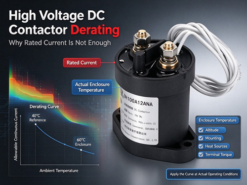
Where the Heat Comes From
A contactor generates heat from two main sources during continuous operation: the main current path and the coil.
Main current path. When the contacts are closed, current flows through the contact interface and the conductive path inside the contactor. Even a contact resistance of a fraction of a milliohm dissipates significant power at high current. At 400 A, 1 mΩ of resistance produces 160 W of heat at the contact interface. That heat must conduct away from the contact area through the contactor body and terminals.
Coil. A conventional DC contactor coil may dissipate 8–15 W continuously while energized. This heat is generated inside the same housing and contributes to the overall thermal load. Coil economizer circuits can reduce holding power to the range of 1.7–4 W, but even that reduced power adds to the thermal budget in a sealed enclosure.
The contactor's temperature rise is the sum of these internal heat sources plus the ambient temperature around it. The design limit is the maximum temperature the contact materials, insulation, and coil can tolerate without accelerated aging or performance drift.
Why the Datasheet Rating Has Conditions Attached
Contactor current ratings are derived from temperature-rise testing. Engineers apply known currents to a fully assembled contactor in controlled ambient conditions, measure the steady-state temperature of the terminals, contacts, and coil, and determine the current at which the temperature rise remains within the material limits.
The resulting rating is valid at the test ambient temperature and under the test mounting conditions. A contactor rated for a given current at 40°C ambient, mounted on a standard test fixture with free air circulation, may not carry that same current at 60°C inside a sealed cabinet. The internal temperature would exceed the test condition, and the material limits would be approached or exceeded.
This is not a defect in the rating—it is a boundary condition. The datasheet tells you what the contactor can do under defined conditions. The application engineer's job is to translate that into what it can do under actual conditions.
The Derating Curve: What It Represents
A derating curve plots allowable continuous current against ambient temperature. As ambient temperature rises, the allowable current decreases. The curve is specific to the contactor design—its contact materials, coil insulation class, thermal mass, and heat dissipation paths.
The curve answers a practical question: at the temperature my contactor will actually see, what current can it carry continuously?
Two complications arise in real applications. First, the "ambient temperature" in the derating curve refers to the air temperature around the contactor, not the outdoor temperature or the room temperature. Inside an enclosure, the air temperature around the contactor can be significantly higher than the external ambient due to heat generated by other components (busbars, fuses, power supplies, inverters) and by the contactor itself. Second, the derating curve assumes a particular mounting and airflow condition. If the contactor is mounted against a surface that blocks heat conduction, or if nearby components radiate heat onto it, the effective derating may be more severe than the curve suggests.
Enclosure Effects: The Hidden Temperature Rise
The gap between external ambient temperature and the air temperature around the contactor is one of the most commonly underestimated factors in contactor selection. In a sealed or poorly ventilated enclosure, internal air temperature can rise well above external ambient. The exact rise depends on the total heat load inside the enclosure, the enclosure surface area, and any ventilation or cooling.
For a contactor rated at a reference ambient of 40°C, operating in an enclosure where the internal air reaches 60°C means the derating must be applied at 60°C, not at 40°C. A contactor that appears to have ample margin on paper may be operating close to its thermal limit once the enclosure effect is accounted for. This is why thermal analysis of the enclosure—not just the contactor datasheet—should inform the current rating decision.
Other Factors That Shift the Thermal Balance
Altitude. Higher altitude reduces air density and therefore reduces convective cooling. Some contactor specifications include altitude correction factors; if the application operates at significant elevation, the derating should account for reduced cooling capacity.
Mounting orientation and nearby heat sources. A contactor mounted near a hot busbar, a power resistor, or an inverter heatsink absorbs radiant and conducted heat from those components. The derating curve assumes the contactor is not subjected to external heat sources beyond ambient air temperature.
Terminal connections. The terminals themselves are part of the heat path. A poorly torqued terminal connection adds resistance and generates additional heat at the connection point. Large busbars connected to the terminals can also conduct heat into the contactor from other parts of the system.
A Practical Derating Selection Process
- Determine the maximum continuous load current. This is the steady-state current the contactor will carry for extended periods, not a transient peak.
- Estimate the actual air temperature around the contactor. Measure or calculate the internal enclosure temperature under worst-case operating conditions, including heat from other components.
- Apply the manufacturer's derating curve at that temperature. If the derated current is below the required load current, the contactor is undersized for the application.
- Account for altitude and external heat sources. If the application operates at altitude or near significant heat sources, apply additional margin beyond the basic temperature derating.
- Verify with a temperature-rise check if possible. In critical designs, measure terminal or case temperature under actual load and enclosure conditions to confirm that the contactor is operating within its thermal limits.
Selection Checklist for Thermal Derating
- Maximum continuous load current identified (not transient peak)
- Internal enclosure air temperature estimated at worst case
- Manufacturer's derating curve applied at the actual internal temperature
- Derated current ≥ required continuous load current
- Altitude correction applied if applicable
- External heat sources near the contactor evaluated
- Terminal torque and connection quality confirmed
- Temperature-rise verification planned or performed for critical designs
FAQ
Why does a contactor need derating if the load current is below its rating?
Because the current rating is valid at a reference ambient temperature and mounting condition. If the contactor operates in a hotter environment, its ability to dissipate heat is reduced, and the current it can carry continuously without exceeding material limits is lower than the reference rating.
What is the difference between ambient temperature and enclosure temperature?
Ambient temperature usually refers to the air temperature surrounding the equipment. Enclosure temperature is the air temperature inside the cabinet or container where the contactor is installed. Heat from other components and from the contactor itself can make the enclosure temperature significantly higher than the external ambient.
How much current margin should I add beyond the derated value?
There is no single figure that applies to all applications. A modest margin—on the order of 10–20% above the calculated derated requirement—provides a buffer for estimation uncertainty in enclosure temperature and load profile. For critical or high-value systems, a larger margin or direct temperature measurement is advisable.
Does a coil economizer change the thermal derating?
It can help, but it does not eliminate the need for derating. A coil economizer reduces holding power, which reduces one heat source inside the contactor. The main current path still generates heat, and the enclosure temperature still drives the derating calculation. The economizer may allow a slightly more favorable thermal operating point, but the derating curve should still be applied based on the actual conditions.
Can I use a contactor at its rated current if I add a cooling fan?
Forced cooling can improve heat dissipation and may allow operation closer to the reference rating, but the effect depends on airflow path and velocity. The manufacturer's derating curve may not account for forced cooling. If forced cooling is used, verify thermal performance through testing rather than assuming the rated current is restored.
How does altitude affect contactor derating?
At higher altitude, air density decreases, which reduces convective cooling. Some manufacturers publish altitude correction factors. If the contactor operates at significant elevation, the derated current should be reduced further to account for the lower cooling capacity.
Conclusion
A high-voltage DC contactor's current rating is a laboratory-derived number tied to specific ambient and mounting conditions. In a real enclosure, heat from the contact path, the coil, and nearby components raises the contactor's operating temperature, reducing the current it can safely carry continuously. The practical approach is to start with the derating curve, apply it at the actual internal enclosure temperature, and then account for altitude and external heat sources. In critical designs, verify the result with a temperature-rise check.
To review high voltage contactor series and their thermal specifications, visit the high voltage DC contactor product page. For help applying derating curves to your specific enclosure and load profile, contact our technical team.