English
  한국어
한국어

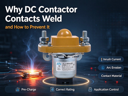
Contact welding is one of the most serious failure modes in a DC contactor. When the main contacts weld together, the contactor cannot open—even when the coil is de-energized. The circuit remains closed, and the system loses its ability to disconnect the load. This article explains what causes contact welding, how to recognize the conditions that lead to it, and what design and application measures can prevent it.
What Is Contact Welding?
Contact welding occurs when the surfaces of the mating contacts fuse together during a switching event. The weld can be a light tack weld that breaks on the next opening attempt, or a solid weld that permanently prevents the contactor from opening.
The root cause is always the same: enough heat is generated at the contact interface to melt or soften the contact material, and the surfaces then fuse as they cool under pressure. The question is where that heat comes from.
The Three Main Causes of Contact Welding
Cause 1: Inrush Current at Closure
This is the most common cause of contact welding in DC systems. When a contactor closes into a capacitive load—such as an inverter's DC link capacitors, a power supply with input filtering, or another contactor's coil suppression network—the discharged capacitors initially present a near short circuit. The resulting current spike can reach hundreds or thousands of amperes in microseconds.
During contact closure, the contacts do not make instantaneous, full-surface contact. They bounce. Each bounce creates a tiny arc that generates localized heating. If the inrush current is high enough, the contact surfaces reach melting temperature during one of these bounces. The result is a weld at the point of contact.
A standard contactor closing directly onto a capacitive load without pre-charge is at high risk of this failure mode. The problem is not the steady-state current—it is the transient at the moment of closure.
Cause 2: Opening Under Load (Arc Erosion)
When a contactor opens while carrying current, an arc forms between the separating contacts. In DC circuits, this arc does not self-extinguish at a current zero as it would in AC. The arc persists until the voltage across the gap can no longer sustain it or until an arc suppression mechanism forces it to extinguish.
The arc transfers material from one contact to the other. Over many switching cycles, this material transfer creates pits and peaks on the contact surfaces. The peaks are the points where the next weld is most likely to occur. Eventually, the cumulative erosion can lead to a weld that the contactor's opening force cannot break.
This failure mode is more common in contactors that frequently open under full load, or that operate at voltages and currents near their maximum rating.
Cause 3: Contact Material and Surface Condition
Contact material selection affects welding resistance. Silver alloys (such as AgCdO and AgSnO₂) are commonly used for DC contactor contacts because they combine good conductivity with resistance to arc erosion and welding. Silver tungsten and copper-tungsten materials offer higher welding resistance but higher contact resistance.
Surface contamination also plays a role. Oxidation, dust, or polymer films on the contact surfaces can increase contact resistance and create localized hot spots during current flow. In some cases, contamination contributes to the welding process by altering the surface condition at the point of contact.
How to Tell If Your Contactor Has Welded
The most direct symptom is a contactor that will not open when commanded. The coil may de-energize and the armature may return to the open position, but the main contacts remain closed. In a system with voltage monitoring, the load side of the contactor will remain energized even after the control signal is removed.
Other signs include:
- The contactor fails to open when the coil is disconnected
- The system cannot be shut down by the normal control sequence
- Continuity is measured across the main contacts in the de-energized state
- The contactor makes a "stuck" sound or feels mechanically bound when manually actuated
If welding is suspected, the contactor should be removed from service. A welded contactor cannot provide the disconnection function it was installed for.
Prevention Method 1: Pre-Charge Circuits
A pre-charge circuit is the standard method for preventing welding from inrush current. The pre-charge circuit uses a resistor in series with a smaller contactor (or a solid-state switch) to limit the initial current when connecting a capacitive load. The sequence is:
- Close the pre-charge contactor. Current flows through the pre-charge resistor and charges the capacitors at a controlled rate.
- When the capacitor voltage reaches a threshold (typically 90–95% of the supply voltage), close the main contactor.
- Open the pre-charge contactor.
With the capacitors already charged, the main contactor closes with minimal voltage difference across its contacts—and therefore minimal inrush current. The risk of welding at closure is greatly reduced.
The pre-charge resistor value and power rating must be selected for the capacitor bank size and the desired pre-charge time. A pre-charge time that is too short will not adequately limit the current; one that is too long may delay system startup unnecessarily.
Prevention Method 2: Correct Contactor Selection
Selecting a contactor with appropriate ratings and features reduces welding risk.
Voltage and current margin: A contactor operating near its maximum voltage or current rating has less margin for transient conditions. For applications with high inrush or frequent switching, consider a contactor with a higher continuous current rating than the steady-state load requires.
Contact material: For applications where inrush current is unavoidable, contact materials with higher welding resistance (such as silver-tungsten) may be preferred, at the cost of slightly higher contact resistance.
Arc suppression design: Contactors designed for high-voltage DC use magnetic blowout, arc chambers, or gas-filled enclosures to extinguish arcs quickly. These features reduce arc erosion and extend contact life.
Contact force and opening mechanism: The force available to break a weld depends on the contactor's mechanical design. Contactors with stronger opening springs and more robust mechanisms are better able to break light tack welds before they become solid welds.
Prevention Method 3: Application and Installation Practices
Avoid repeated close-open cycling under load: Frequent switching under full load accelerates arc erosion. If the application requires frequent switching, consider whether a different switching device (such as a solid-state relay for low-power circuits) would be more appropriate.
Maintain terminal torque: Loose terminal connections create resistance and heat. While this does not directly cause contact welding, it contributes to overall thermal stress on the contactor.
Keep the contactor within its environmental ratings: High ambient temperatures reduce the contactor's current-carrying capacity and can affect the mechanical properties of the contact system. Ensure the installation environment is within the specified operating range.
Inspect contacts periodically: For contactors in critical applications, periodic inspection of contact surfaces can reveal erosion patterns before they lead to welding. Contact resistance measurement is a practical field check—a rising contact resistance indicates surface degradation.
Prevention Checklist
- Pre-charge circuit installed for capacitive loads
- Pre-charge resistor and timing verified for the capacitor bank
- Contactor voltage rating exceeds system voltage with margin
- Continuous current rating has margin above steady-state load
- Contact material suitable for expected inrush conditions
- Arc suppression design appropriate for system voltage
- Terminal connections torqued to specification
- Ambient temperature within contactor rating
- Periodic contact resistance inspection included in maintenance schedule
FAQ
What is contact welding in a DC contactor?
Contact welding is a failure mode where the main contacts fuse together and cannot open. The contactor remains in the closed state even when the coil is de-energized, preventing the system from disconnecting the load.
What causes contact welding?
The three main causes are inrush current at closure (especially into capacitive loads without pre-charge), arc erosion from opening under load, and contact material or surface conditions that promote localized heating.
How can I prevent contact welding from inrush current?
Use a pre-charge circuit. The pre-charge resistor limits the initial current while the capacitors charge. The main contactor closes only after the capacitor voltage is close to the supply voltage, eliminating the high inrush transient.
Can a welded contactor be repaired?
In most cases, a welded contactor cannot be reliably repaired in the field. The contact surfaces have been damaged, and the welding indicates that the contact system has experienced conditions beyond its design limits. The contactor should be replaced, and the root cause—such as an undersized pre-charge circuit—should be addressed.
How do I check if my contactor contacts are welded?
With the contactor de-energized and disconnected from power, measure resistance across the main contacts. Normally open contacts should show an open circuit. If they show continuity, the contacts are welded. In a powered system, the load side will remain energized after the coil is de-energized.
Does contact welding happen immediately or over time?
It can happen either way. A severe inrush event can cause welding in a single closure. Arc erosion from repeated switching under load causes cumulative damage that eventually leads to welding after many cycles.
Conclusion
Contact welding is a serious failure mode, but it is largely preventable. The most important preventive measure is a properly designed pre-charge circuit for any application where the contactor closes into a capacitive load. Correct contactor selection—with adequate voltage and current margin, suitable contact material, and appropriate arc suppression—addresses the remaining risk factors.
If a contactor has welded, replace it and investigate the cause. Welding is a symptom of an application condition that exceeds the contactor's design limits. To review DC contactor specifications and selection guidance, visit the DC contactor product page. For help evaluating whether your application requires a pre-charge circuit or a contactor with different characteristics, contact our technical team.